Controller Wi-Fi 2 - Installation Manual
Description
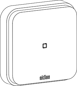
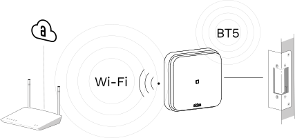
Akiles Controller Wi-Fi is a Cloud access control system that enables the management of any electric door opener and/or automation device through a connection to Akiles Cloud via the existing Wi-Fi network available at the installation site.
It is the first Cloud system on the market to feature an integrated backup battery, providing several days of autonomy and ensuring continuous operation and secure access even in the event of a power outage*.
Capabilities
Akiles Controller Wi-Fi is designed to:
- Control any electric door opener and/or automation system (building entrance doors**, motorized shutters***, parking doors***, automatic doors, or sliding doors).
- Read the status of Akiles wireless sensors (Akiles Frame) and wired sensors (contact, presence, infrared, or temperature sensors).
- Connect Akiles Cloud to other Akiles devices.
Key features
- Compact device with an integrated rechargeable battery, avoiding the use of external batteries or UPS systems, and simplifying installation of a backup-powered system in the event of power outages.
- Device designed to minimize power consumption, extending battery life (Low Power).
- Proprietary SmartDriver technology dynamically adapts the power supplied to the connected electric door opener, optimizing energy consumption.
- Up to 6 days of uninterrupted operation in the absence of a power supply.
- During a power outage, access remains 100% operational and online.*/****
* In the event of a power outage, the device will still allow offline openings via BT thanks to its backup battery. To ensure 100% Cloud operation, it is recommended to have a backup system for the Wi-Fi router.
** For building entrance doors, opening will only be possible with a Controller Wi-Fi installed directly on the building entrance door electric door opener.
*** Opening in the absence of power supply is not available for motorized shutters or parking doors.
**** Administrators will be notified in the event of a power outage, a particularly useful feature for unattended assets.
Box Contents
| Item | Preview |
|---|---|
| x1 Akiles Controller Wi-Fi | 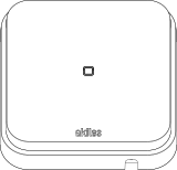 |
| x1 Security key |  |
| x1 Opening tool |  |
| x2 Wall anchors (for 6 mm drill bit) |  |
| x2 Self-tapping screws |  |
| x1 Security fixing screw |  |
Composition
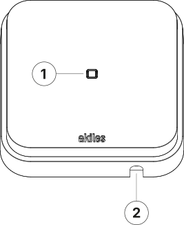
- 1. RGBW LED (status)
- 2. Cable pass-through hole
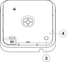
- 3. Security screw hole
- 4. Reset (factory settings)
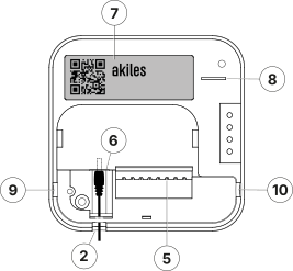
- 5. Connection pins
- 6. Power jack (5.5 × 2.1 mm)
- 7. Serial number label
- 8. Slot for battery insulating strip
- 9. Cable pass-through hole (openable)
- 10. Cable pass-through hole (openable)
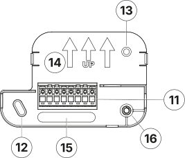
- 11. Plug-in terminal block (8 poles)
- 12. Wall mounting holes
- 13. Wall mounting hole
- 14. Plate orientation (upwards)
- 15. Cable pass-through hole
- 16. Insert for security screw
Technical Specifications
| Characteristic | Specification |
|---|---|
| Modes | Online (with Internet connection) and Offline (without Internet connection) |
| Mounting | Standalone/Wall (optional) Surface wall installation using a wall plate with security screw |
| Color | White RAL 9003 |
| Signaling | 1 light indicator (RGBW LED) and 1 sound indicator (Buzzer) |
| Power Supply | 12 Vdc ± 15% / 1.5 A (5.5 × 2.1 mm jack or terminal block) Internal rechargeable battery |
| Maximum consumption | < 1 W |
| Rechargeable Battery | 1 Li-ion cell, 1500 mAh capacity Charging time: 4 hours (0% → 100%) Protections: Overcharge, over-discharge, overcurrent, and short circuit JEITA charging profile with temperature protection |
| Backup time | Up to 6 days |
| Outputs | 1 SmartDriver output (terminals Lock/Lock) and 1 relay output (terminals C/NO) |
| SmartDriver Output Features | Output for direct connection to an electric door opener (terminals Lock/Lock) Compatible with any electric door opener with a coil impedance between 1 and 100 Ω |
| Relay Switching Capacity | 30 Vdc (max. 2 A) Terminals C (Common) and NO (Normally Open) |
| VOUT Output | 12 Vdc ± 15% output (max 1 A) with backup against power supply interruptions, for powering other devices |
| Sensor Input | For a push button or sensor with potential-free output (dry contact) |
| Connectivity | BT (5.0, 4.x) Wi-Fi (IEEE 802.11 b/g/n) |
| Firmware updates | Over-the-Air (OTA) |
| Materials | ABS V0 and PC |
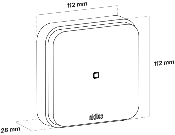
| Dimensions | 112 x 112 x 28 mm |
| Weight | 230 g |
| Temperature Range | 0..+45ºC |
| Humidity Range | 10..90% (non-condensing) |
| IP Rating | IP20 (indoor use only) |
| Terminal Capacity | 0.2 < mm² < 2.5, push-in terminals (no screw) |
Light Indicator Signals (RGBW LED)
Device Operating Correctly
| Color | Blinking | Meaning |
|---|---|---|
| White | No | Started, everything OK |
| White | Slow | Started, everything OK (operating on backup power) |
Action Performed (Unlock)
| Color | Blinking | Meaning |
|---|---|---|
| Green | — | Unlock performed |
Device Startup Type
| Color | Blinking | Meaning |
|---|---|---|
| Red | No | Reset |
| Red | Fast | Restoring factory settings |
Internet Connection Issues
| Color | Blinking | Meaning |
|---|---|---|
| Purple | 1 | Wi-Fi network not found or incorrect password |
| Purple | 2 | Wi-Fi OK, DHCP Error |
| Purple | 3 | Wi-Fi OK, DHCP OK, DNS Error |
| Purple | 4 | Wi-Fi OK, DHCP OK, DNS OK, Connection Error |
BT Connection Issues
| Color | Blinking | Meaning |
|---|---|---|
| Yellow | 1 | No connection received from Gateway |
| Yellow | 2 | No connection with Controllers / Cylinders / Roomlocks / Pinpads |
Dimensions
Terminal Block Nomenclature
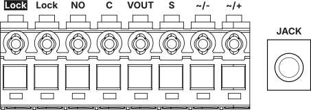
| Terminal | Description |
|---|---|
| Lock, Lock | Direct connection to an electric door opener |
| NO, C | Relay connections (NO: normally open, C: common) |
| VOUT | 12 Vdc ± 15% power output with backup against power supply failures |
| S | Sensor input with dry contact / potential-free output (2 states) |
| ~/+, ~/- | 12 Vdc ± 15% power input |
| JACK | Input for 12 Vdc ± 15% power adapter (1.5 A) |
Installation Diagrams
Diagram 1: Electrified door + Intercom + Sensor/Button
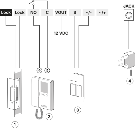
The diagram shows the typical connection with:
- 1. Electric door opener
- 2. Intercom (automation)
- 3. Sensor/button
- 4. 12 VDC ± 15% / 1.5 A Power Supply
Diagram 2: Installation of a Controller in parallel with an Intercom System (door station)
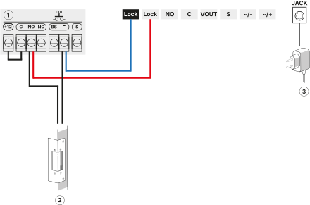
The diagram shows:
- 1. Previously installed system with which to share the management of an electric door opener
- 2. Electric door opener
- 3. 12 VDC ± 15% / 1.5 A Power Supply
In this way, it is possible to have backup in case of power supply outages for the building’s access electrified door.
Important: It is very important to respect the polarity shown in the previous figure (Lock connected to the negative of the other system and the Lock terminal connected to the normally open contact of the existing system’s relay).
Diagram 3: Installation of 2 electric door openers
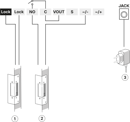
The diagram shows:
- 1. Electric door opener #1
- 2. Electric door opener #2
- 3. 12 VDC ± 15% / 1.5 A Power Supply
Considerations:
- Both door openers will have backup in case of power supply outages.
- With this configuration, the backup time is significantly reduced compared to the typical installation (connection of a single door opener to the Lock/Lock terminals).
- For the door opener connected to the Lock/Lock terminals, any type of electric door opener is suitable, with any coil impedance (from 1 Ω to 100 Ω).
- For the door opener connected to the relay, a door opener with a minimum impedance of 40 Ω is recommended, due to the current limitation of the VOUT output when the device’s internal battery is active (in the absence of mains power).
- It is recommended to verify that the simultaneous activation of both door openers works properly. If not, use a door opener (#2) with lower power consumption or use a power supply with higher current capacity.
Considerations Before Installation
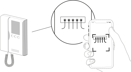
Consideration 1: When wiring the Akiles Controller Wi-Fi to an automation system, such as an intercom monitor or a motorized blind control panel, it is recommended to take a photo of the wiring as it is before installation. This can be useful later, when connecting the device to the automation system.
Consideration 2: The wire gauge used to connect the Akiles Controller Wi-Fi to an electric door opener and/or automation system must be appropriate for its/their power consumption.
Consideration 3: The recommended maximum distance between the router or AP generating the Wi-Fi signal and the Akiles Controller Wi-Fi device is 15 m. It is important to note that walls and large objects in between may negatively affect the communication range between the devices.
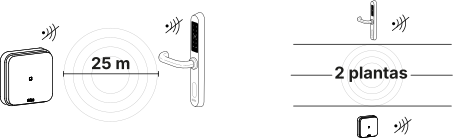
Consideration 4: If the Akiles Controller Wi-Fi device needs to provide coverage to other Akiles devices via BT, the distance between them should not exceed 25 m on the same floor, and devices should not be separated by more than 2 floors, to ensure proper wireless coverage.
Consideration 5: Once the device is installed and properly configured, it is recommended to wait 3 to 5 minutes to allow the device to start correctly, connect to Akiles Cloud, and download the latest available firmware version.
Consideration 6: It is strongly recommended that the installation of this device be carried out by an authorized Akiles electrical installer.
Device Installation
- Attach the wall plate at the desired location.
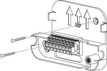
- Make the appropriate connections to the terminals of the wall plate, according to the provided installation diagrams.
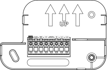
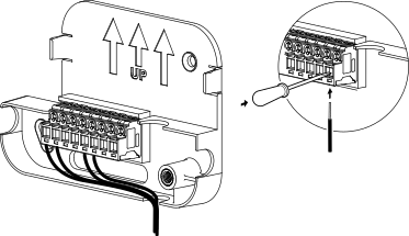
- Make the necessary connections on the device (relays, power supply).
⚠ Important: Before proceeding to the next step, make sure that the device’s power supply has been connected. Following this sequence ensures a correct installation of the device.
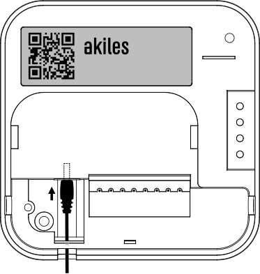
- Remove the protective battery strip. Note that the device is delivered with a protective battery strip, so to activate the battery, the strip must be removed from the slot marked as (8) in the Composition section.

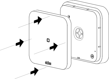
- Insert the device into the wall plate. The wall plate has a metal threaded insert (16). To secure the device to the wall, insert the supplied security screw into the hole marked as (3), so that the assembly is firmly anchored to the wall.
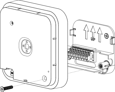
- Verify correct orientation. The front cover must be inserted so that the Akiles logo is readable.
Wi-Fi Network Settings
The procedure for configuring the Wi-Fi network on the device, which must have been previously registered in the administration panel, is as follows:
1. Use your mobile phone to create a hotspot named “AkilesSetup” with the password “GoToTheCloud”.
Enable the option to share your internet connection via Wi-Fi on your phone. The exact location of this setting in your phone’s configuration depends on the operating system version and the manufacturer’s customization layer.
Android example:
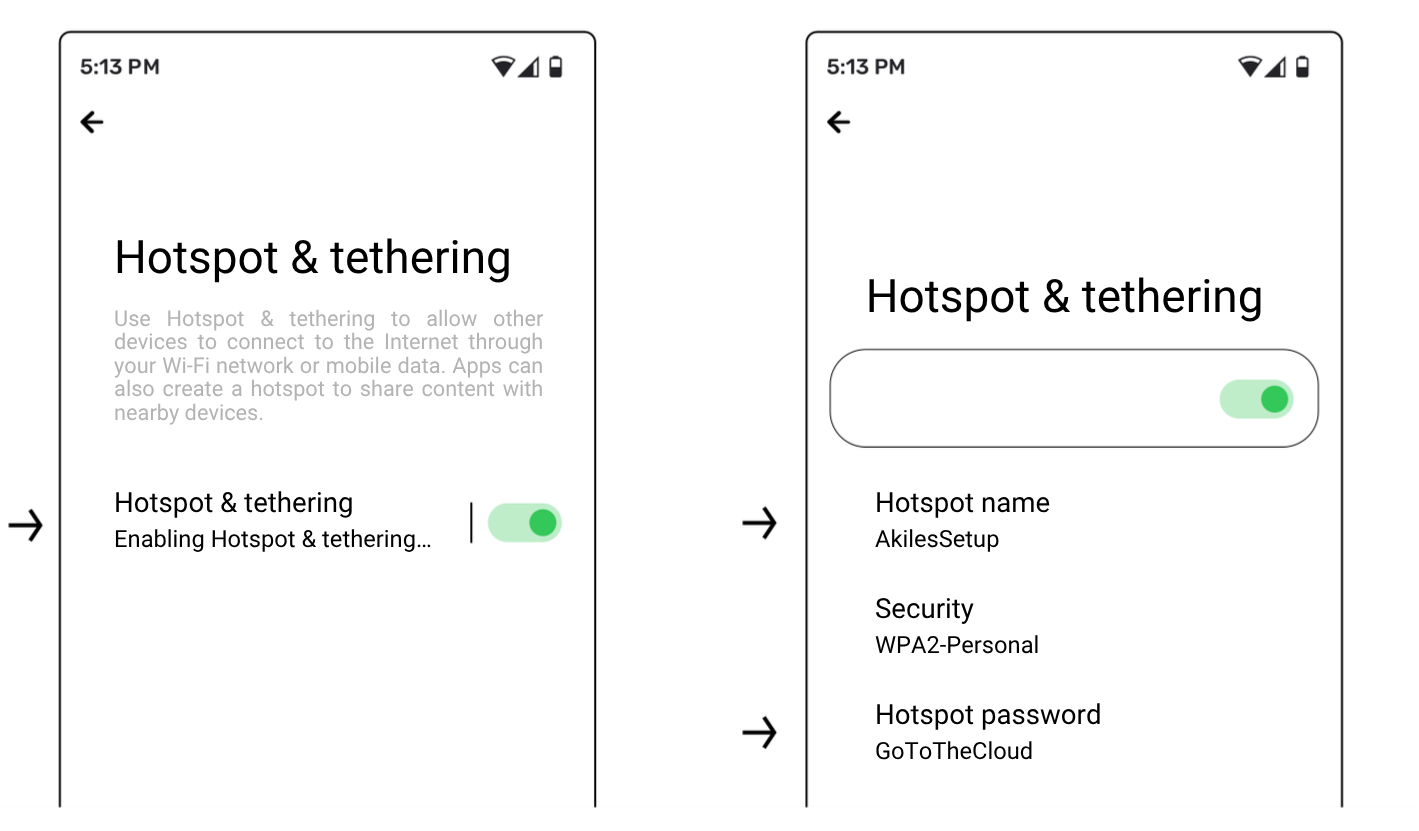
Go to Settings > Network & Internet > Enable “Hotspot & tethering” > Tap “Hotspot & tethering” > Set the hotspot name to “AkilesSetup” > Set the hotspot password to “GoToTheCloud”.
iOS example:

- Go to Settings > General > About > Name > Change it to “AkilesSetup”.
- Go to Settings > Personal Hotspot > Turn on “Allow Others to Join” > Set the Wi-Fi Password to “GoToTheCloud”.
Once this process is completed, the Akiles Controller Wi-Fi will automatically connect to the network provided by your phone.
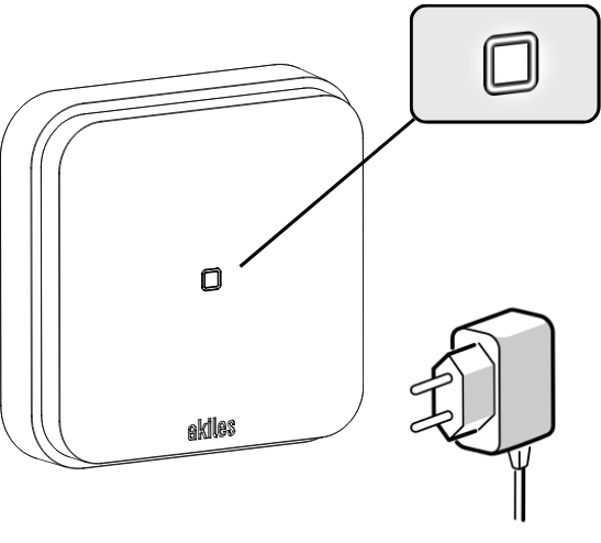
2. After powering on the Akiles Controller Wi-Fi, the status LED should be solid white (no blinking). If this is not the case, check and repeat the previous step.
3. In the administration panel, go to your organization’s Locations tab and select the device location. Click the “Wi-Fi Networks” button.
4. Enter the name (network identifier or SSID) and password of the space’s Wi-Fi network. To finish, click the “Create” button.
5. Wait until the Controller Wi-Fi appears in the Devices tab of the Admin Panel with the status Online, rather than “Configuration pending”. The corresponding percentage indicating the charge level of the device’s integrated rechargeable battery should also be displayed alongside the status indicator.

6. Disable the hotspot on your mobile phone, stopping Internet sharing.
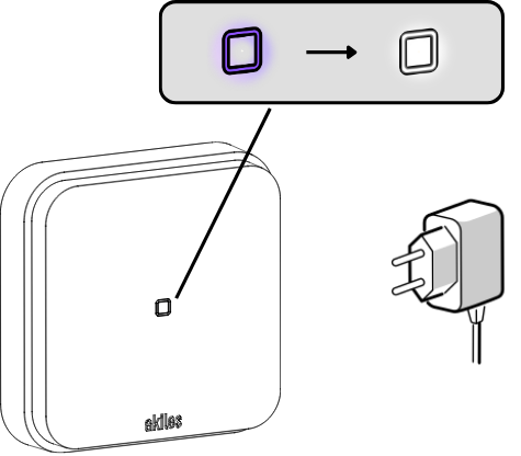
7. The Akiles Controller Wi-Fi status LED should appear purple and blink for a few seconds while connecting to the Wi-Fi network. Once connected, the LED will remain solid white and the device will be ready for operation.
For security reasons, once the device has connected to the site’s Wi-Fi network, it will no longer connect to an access point using the default credentials (“AkilesSetup”/“GoToTheCloud”). To do so, the device must be reset to factory settings and the previously described process must be repeated.
If you perform a factory reset on your wireless router or change the Wi-Fi network password, the Controller Wi-Fi will not be able to connect to the Akiles Cloud. For this reason, any changes must be anticipated and the new credentials (SSID and password) must be entered in the administration panel (“Locations” tab → Device location → “Wi-Fi Networks”).
Legal Information
Wireless Product Specifications
BT5/BT4 frequencies (communication with user smartphone): 2400–2483.5 MHz (Max. 10 dBm)
Akiles proprietary protocol frequencies (communication between devices): 2400–2483.5 MHz (Max. 20 dBm)
Wi-Fi frequencies: 2400–2483.5 MHz (Max. 18 dBm)
Radiofrequency Exposure Information (Maximum Permitted Exposure)
This device complies with EU requirements regarding the limitation of exposure of the general public to electromagnetic fields in order to protect health. To meet radiofrequency exposure requirements, the equipment must be used at a minimum distance of 20 cm from the user.
Regulations and Certifications


The WEEE symbol (Waste Electrical and Electronic Equipment) indicates that this device and batteries (if incorporated) should not be disposed of with other household waste.
When the product reaches the end of its useful life, take it to a waste collection point in your area for safe disposal or recycling.
This product complies with the provisions of the European Radio Equipment Directive (2014/53/EU).
This product also complies with the essential requirements of Directive 2011/65/EU (RoHS 2), 2012/19/EU (WEEE) and EU regulation No. 1907/2006 (REACH).
Safety Information
⚠ This device contains a rechargeable lithium-ion battery. Read the following recommendations carefully before installing or using the equipment.
Akiles Technologies S.L. is not responsible for damages resulting from improper use, incorrect installation, or failure to comply with the safety recommendations indicated in this manual.
Intended use
- This product is designed exclusively for indoor use:
- Do not use outdoors or in humid environments (max. 90% RH).
- Do not expose to liquids, splashes, or condensation.
Environmental conditions
- Use the device only within the temperature range specified by the manufacturer (0–+45 °C).
- Do not install the equipment near radiators, heaters, or other heat sources. Do not expose the device to direct sunlight for prolonged periods.
- Ensure adequate ventilation around the equipment. Do not cover the device or obstruct the rear ventilation slots.
Handling
- The user must not dismantle, manipulate, open, or modify the device under any circumstances.
Power supply
- Preferably use the power supply recommended by Akiles, or otherwise use a power supply that complies with the voltage and current values specified in this document.
Internal battery instructions
- The internal battery must not be replaced by the user under any circumstances. If necessary, removal of the rechargeable lithium-ion battery of this product must be carried out by a qualified professional.
Storage
- Store the device in a cool, dry place, protected from direct sunlight.
Product recycling
- Do not dispose of in household waste. The product and its battery must be taken to an authorized recycling point in accordance with applicable regulations on electrical and electronic waste.